E-Test
Precision electrical testing (E-Test) for PCB/PCBA assemblies—verifies circuit continuity, insulation resistance, and functional integrity to catch shorts, opens, and component faults early.
✅ Continuity & insulation resistance checks
✅ Detects shorts, opens & component defects
✅ IPC-compliant, fast turnaround
✅ Scalable for prototyping & mass production
Description
What is PCB Electrical Testing?
PCB Electrical Testing refers to a series of standardized procedures designed to verify the electrical functionality and connectivity of a printed circuit board (PCB) after manufacturing. Its core purpose is to detect defects that may cause performance failures, such as open circuits, short circuits, incorrect component placements, or faulty solder joints, before the PCB is assembled into a final product.
The primary goal of PCB electrical testing is to identify any defects, shorts, opens, or other electrical issues that could compromise the performance or reliability of the circuit board.
PCB Electrical Testing Types
PCB electrical testing encompasses a range of specialized methods to verify board connectivity, component functionality, and compliance with design specs. Below are the most common testing types, organized by core purpose and application scenarios:
1. In-Circuit Test (ICT)
· Core Principle
Uses a bed-of-nails fixture—a custom plate with spring-loaded pins that contact pre-defined test points on the PCB. It applies low-voltage/current signals to measure component values, check polarity, and detect open/short circuits between nets.
· Key Advantages
High test speed, high accuracy, and suitability for high-volume production.
· Application Scenarios
Mass-produced consumer electronics, automotive PCBs, and boards with dense, standardized test points.
· Limitations
Fixture costs are high; not ideal for prototypes or low-volume runs.
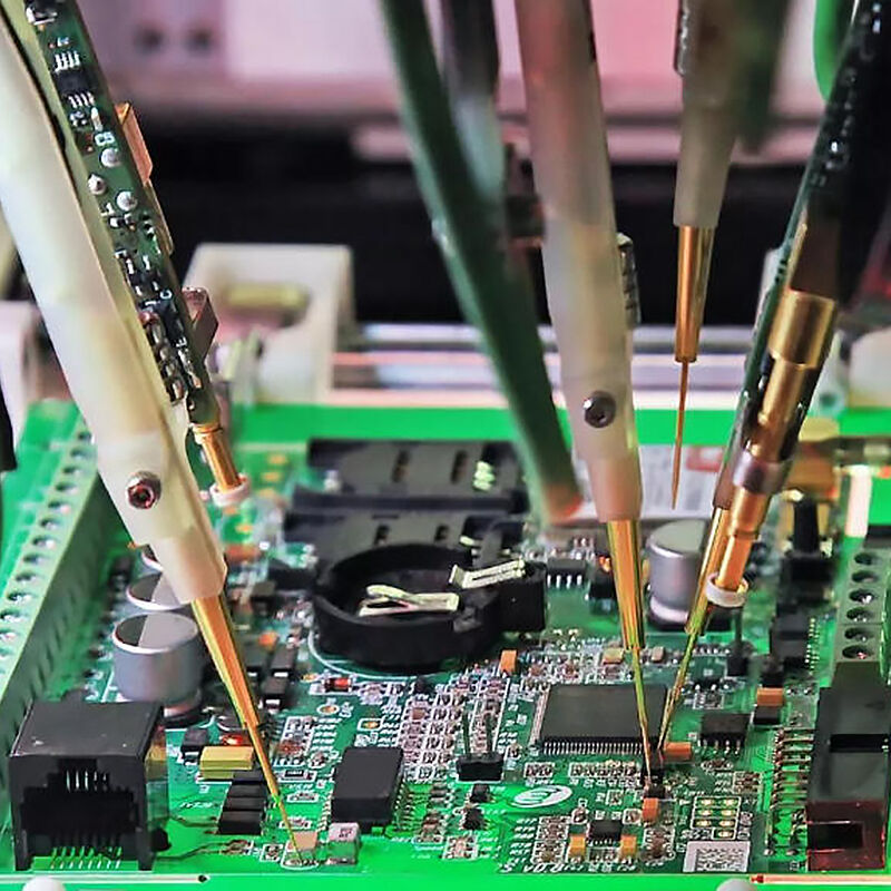
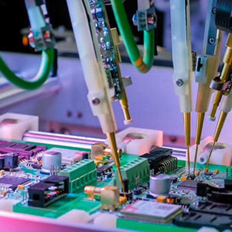
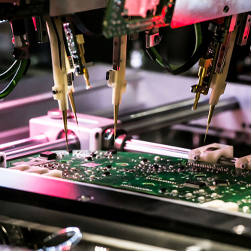
2. Flying Probe Test (FPT)
· Core Principle
Relies on movable, programmable probes instead of a fixed fixture. Probes move across the PCB surface to access test points, performing continuity, resistance, capacitance, and diode tests.
· Key Advantages
No custom fixture required, flexible for complex layouts, and cost-effective for small batches.
· Application Scenarios
PCB prototypes, low-to-medium volume production, high-density boards, and boards with limited test points.
· Limitations
Slower than ICT; not optimal for ultra-high-volume manufacturing.
3. Functional Test (FCT)
· Core Principle
Simulates the actual operating environment of the assembled PCB (PCBA). It applies real-world input signals and verifies if the board outputs match design requirements.
· Key Advantages
Validates end-to-end functionality; ensures the PCB works as intended in a final product.
· Application Scenarios
Final validation of critical PCBs.
· Limitations
Test setup is complex; requires custom programming for each PCB design.
4. Continuity Test
· Core Principle
A basic, low-cost test that checks if two points on a PCB are electrically connected. A tester sends a small current through a trace—if current flows, the path is continuous; if not, an open circuit is detected.
· Key Advantages
Fast, simple, and requires minimal equipment.
· Application Scenarios
Prototype debugging, spot checks during manual assembly, and verifying simple PCB layouts.
· Limitations
Only detects connectivity issues; does not test component functionality.
5. Boundary Scan Test (BST / JTAG Test)
· Core Principle
Uses JTAG (Joint Test Action Group) standards and built-in test circuits on ICs with boundary scan capabilities. It tests interconnections between ICs without physical test points.
· Key Advantages
Ideal for high-density, fine-pitch PCBs where physical access to test points is difficult.
· Application Scenarios
PCBs with complex ICs, aerospace, and military electronics.
6. Automated Optical Inspection (AOI) & Automated X-Ray Inspection (AXI)
Though classified as visual/imaging tests, they often complement electrical testing:
AOI: Uses high-resolution cameras to detect solder defects and component placement errors before electrical testing.
AXI: Uses X-rays to inspect hidden solder joints that are inaccessible to probes or cameras.
Common Types of PCB Electrical Testing
| Test Type | Core Principle | Application Scenarios | |||
| In-Circuit Test (ICT) | Uses a bed-of-nails fixture to contact test points on the PCB; measures component values, continuity, and polarity by applying small test voltages/currents. | High-volume production of PCBs with dense test points; ideal for detecting component placement errors, solder defects, and value mismatches. | |||
| Flying Probe Test (FPT) | Employs movable probes (instead of a fixed fixture) to access test points; programmed to perform continuity, resistance, capacitance, and diode tests. | Low-to-medium volume production, prototype PCBs, or boards with complex layouts that are not cost-effective for ICT fixtures. | |||
| Functional Test (FCT) | Simulates the actual operating environment of the PCB; applies input signals and verifies output responses against design specifications. | Final validation of PCBA functionality; ensures the board works as a complete unit. | |||
| Continuity Test | A basic test that checks if two points on a PCB are electrically connected by detecting current flow between them. | Quick validation of trace connectivity during prototype debugging or spot checks. | |||
Why PCB Electrical Testing Is Crucial and How It Matters to You
PCB electrical testing isn’t just a “factory quality step”—it’s a critical process that directly impacts product reliability, cost savings, and performance for everyone from manufacturers to end-users. Whether you’re a PCB buyer, product designer, or consumer, here’s why it matters:
Catches Defects Early to Slash Costs
Manufacturing defects are inevitable—but detecting them before a PCB is assembled into a final product eliminates costly rework, replacements, and production delays.
· For manufacturers: Avoids warranty claims, product recalls, and damage to brand reputation. A single faulty PCB in a high-volume product can lead to millions in losses.
· For you: Ensures you receive PCBs that meet your specs—no more wasting time troubleshooting boards that should have worked out of the box. You’ll cut development cycles and reduce the risk of project delays.
Guarantees Product Reliability & Safety
Faulty PCBs are a major cause of product failures and safety hazards:
A shorted trace in a power supply PCB can cause overheating, fires, or electric shocks.
An open circuit in a medical device PCB could lead to life-threatening malfunctions.
A mismatched resistor in an automotive PCB might disable critical systems.
Electrical testing verifies that every PCB functions exactly as designed, ensuring products are safe to use and reliable over their lifespan. For you, this means peace of mind—whether you’re building a prototype or shipping a million units to customers.
Ensures Compliance with Industry Standards
Most industries have strict standards for PCB quality. Electrical testing is a mandatory step to meet these standards and gain regulatory approval.
· For businesses: Compliance is non-negotiable to sell products in global markets. Without proper testing, your products could be banned from sale or face legal penalties.
· For end-users: Compliance means you’re buying products that meet rigorous quality and safety benchmarks—no cutting corners on performance.
Improves Production Efficiency & Consistency
Electrical testing streamlines production by:
Eliminating manual inspection errors.
Ensuring every PCB in a batch meets the same quality standards—no “hit-or-miss” performance.
For you, this translates to consistent product performance: every PCB you order will work the same way, reducing variability in your own production or projects.
Saves You Time & Headaches Down the Line
Imagine integrating a faulty PCB into your product, only to discover the issue after assembly, testing, or even customer delivery. The time and cost to diagnose, replace, and re-test the product are massive.
Electrical testing shifts this burden to the PCB manufacturer, catching defects before the board leaves the factory. For you, this means:
Fewer design iterations and troubleshooting sessions.
Faster time-to-market for your products.
Happier customers who don’t experience product failures.

