Metal Core PCB
High-performance Metal Core PCBs for thermal management & high-power applications (LEDs, automotive, industrial, consumer electronics). Excellent heat dissipation, durable metal substrate (aluminum/copper), 24h prototyping, fast delivery, DFM support & strict testing. Reliable, thermally efficient—ideal for power-dense electronics.
✅ Superior heat dissipation
✅ 24h prototyping | fast delivery
✅ DFM & quality testing
✅ LED/automotive/industrial focus
Description
What is a Metal Core PCB?
Metal Core PCB is a special type of printed circuit board that uses a metal material (commonly aluminum, copper, or iron alloy) as the core layer of the substrate. Its typical structure consists of a metal core layer, an insulating layer (high thermal conductivity material), and a circuit layer. Its core advantage lies in its superior heat dissipation performance—the thermal conductivity of the metal core layer is much higher than that of the traditional FR-4 substrate, which can quickly conduct the heat generated by high-power components. At the same time, it has good mechanical strength and electromagnetic shielding properties, and can also integrate heat dissipation and structural support functions, simplifying product design. This type of PCB is widely used in LED lighting, automotive electronics, power electronics, and medical, aerospace and other fields with stringent requirements for heat dissipation and stability. Compared with traditional FR-4 PCB, although the cost is higher, it is irreplaceable in high-heat and harsh operating conditions, while traditional FR-4 is more suitable for ordinary low-power devices.
Product Series
Kingfield offers a variety of metal-based PCBs to meet the needs of different industries and applications.
 |
 |
 |
|
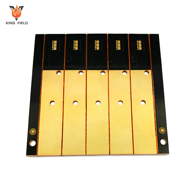
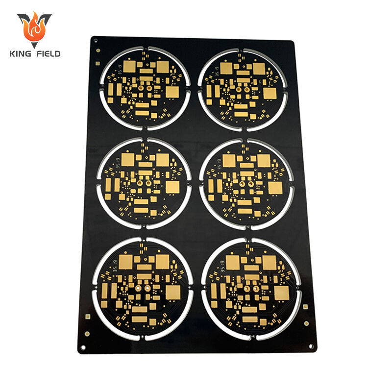
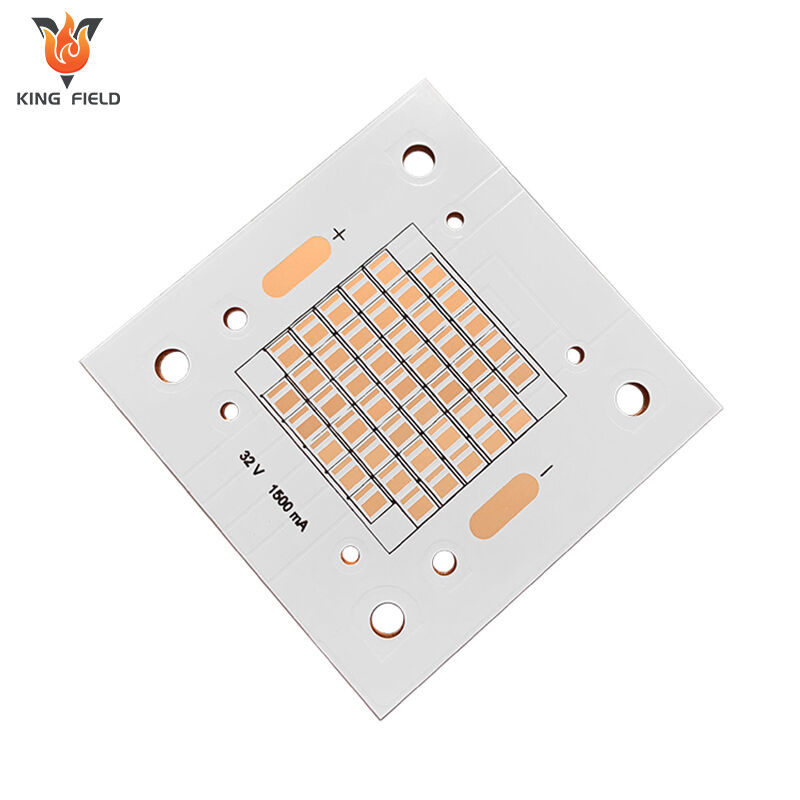
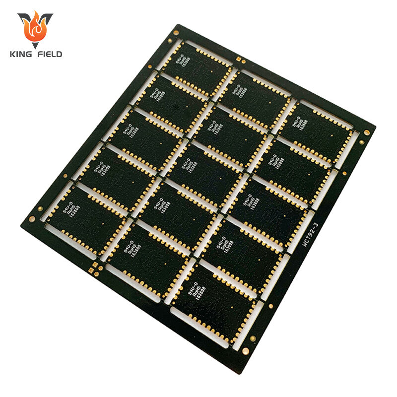
Aluminum Core PCB
|
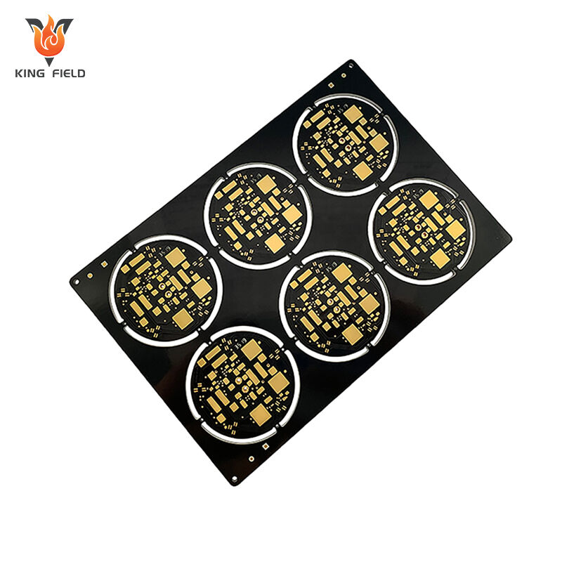
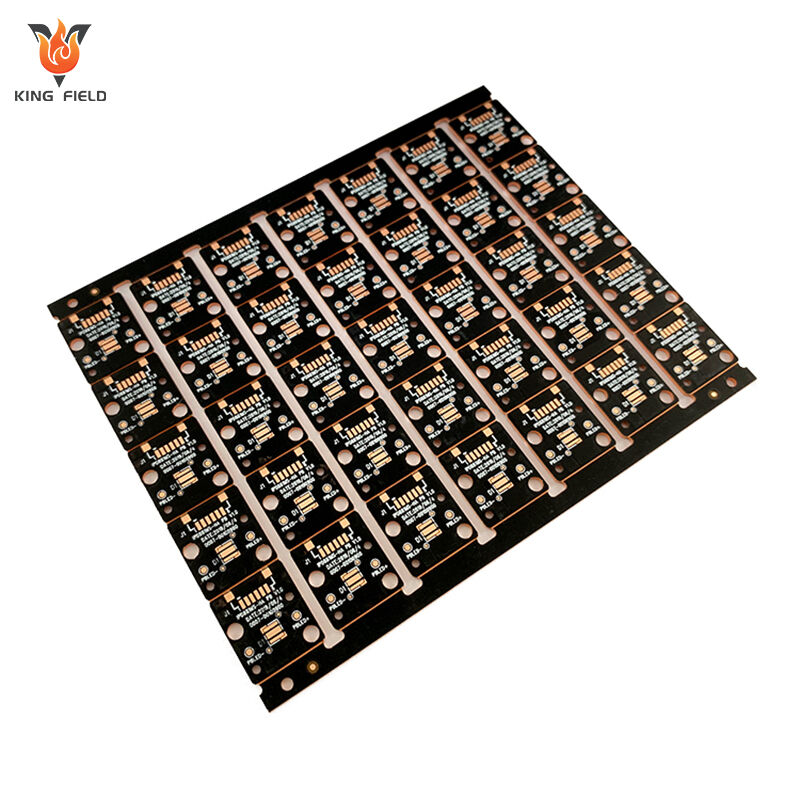
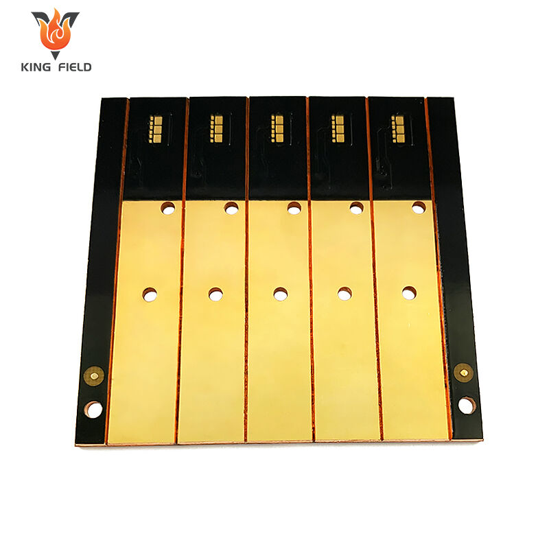
Copper Core PCB
|
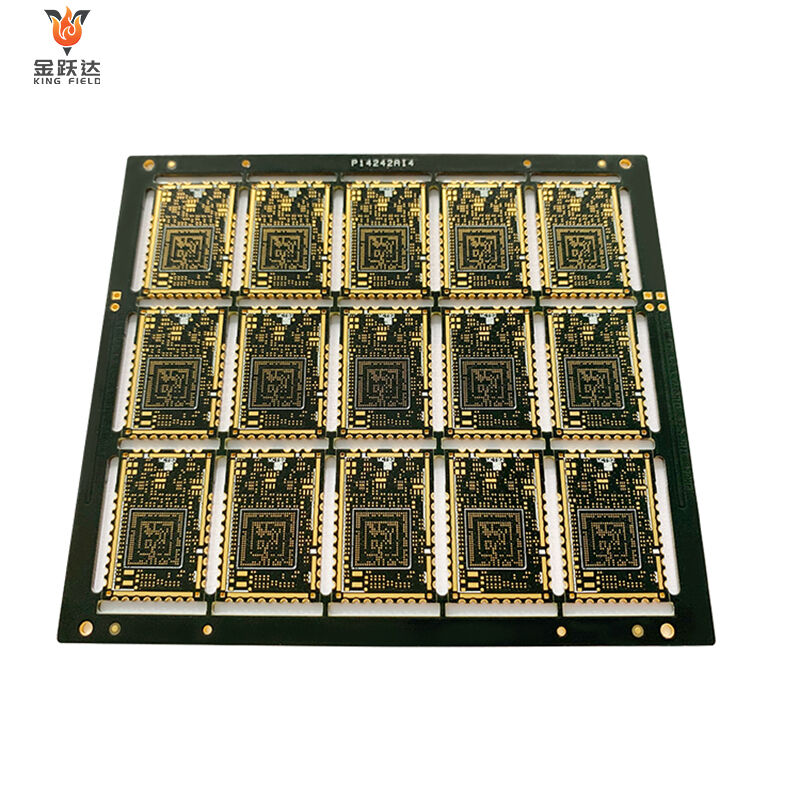
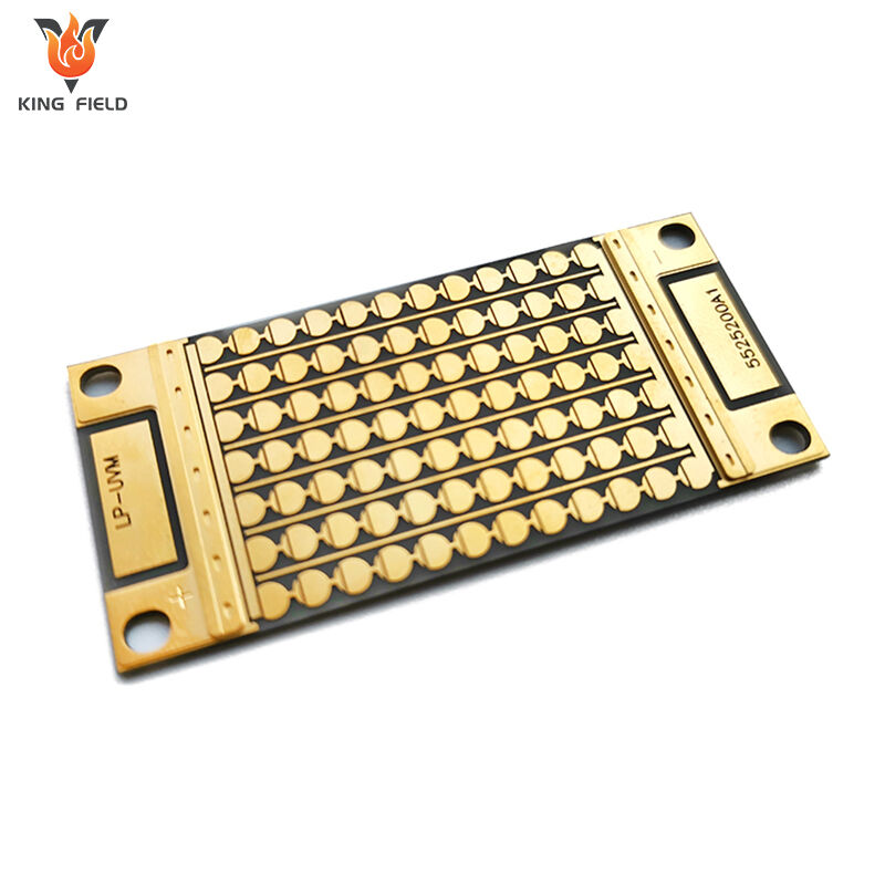
Thermoelectric Separation Copper Substrate
|
Commonly used substrates
| Comparison table of commonly used metal substrates for metal core PCBs | |||||
| Comparison Dimensions | Aluminum (Al) | Copper (Cu) | Ferroalloys/Stainless Steel | ||
| Core positioning | Mainstream general-purpose substrate, cost-effective choice | High-end, ultimate heat dissipation substrate | Special working condition structural base material | ||
| thermal conductivity | Approximately 100-200 W/(m・K) | Approximately 380 W/(m・K) | Lower (far lower than aluminum and copper) | ||
| Cost level | Low cost, abundant raw material reserves, and low procurement costs. | High, precious metal properties, significantly higher cost than aluminum | Medium to high quality, varying depending on the specific alloy composition. | ||
| Mechanical properties | It has good resistance to deformation and vibration, is dimensionally stable, and is relatively lightweight. | High mechanical strength, but heavy weight | Extremely high mechanical strength and strong corrosion resistance | ||
| Processing difficulty | Low cost, good ductility, easy to cut/stamp/bend, and with mature surface treatment technology. | In China, the processing technology requirements are relatively high, which increases the cost accordingly. | High hardness, high processing difficulty | ||
| Typical application scenarios | LED lighting (streetlights, car headlights), general automotive electronics, switching power supplies, and other mass-market commercial applications. | Applications with extreme heat dissipation requirements, such as high-power RF amplifiers and high-end aerospace electronic devices. | Special operating conditions, such as control modules in extreme industrial environments, require extremely high structural stability. | ||
| Core advantages | With balanced overall performance and excellent cost-effectiveness, it is suitable for most scenarios. | Top-notch heat dissipation performance | Stable structure and strong corrosion resistance | ||
| Main disadvantages | Its heat dissipation performance is inferior to that of copper. | High cost and heavy weight | Poor heat dissipation performance and high processing difficulty | ||
Technical Features
Kingfield metal-based PCBs utilize advanced technology and stringent quality control to ensure product performance and reliability.
- Metal-based PCBs have significantly higher thermal conductivity than traditional FR4 PCBs, effectively reducing the operating temperature of electronic components and improving equipment reliability and lifespan.
- Excellent heat dissipation performance allows for higher power density designs, making electronic devices smaller and lighter while maintaining high performance.
- Lowering the operating temperature can significantly improve the reliability and lifespan of electronic components, and reduce equipment failure rates and maintenance costs.
- Metal-based PCBs have excellent heat dissipation properties, which can simplify or eliminate additional heat dissipation devices, reducing system cost and complexity.
- Lower operating temperatures can improve the performance of electronic components, reduce the impact of temperature on performance, and enable the equipment to operate stably over a wider temperature range.
- Metal-based PCBs can serve as structural supports, reducing overall thickness and weight, enabling more compact designs, and are particularly suitable for space-constrained applications.
Advantages
The core advantages of Metal Core PCB:
- Strong heat dissipation: The thermal conductivity of the metal core is far higher than that of traditional substrates, quickly dissipating heat to ensure stable equipment operation and extend lifespan;
- Good mechanical properties: Resistant to deformation and vibration, dimensionally stable, and adaptable to harsh environments such as automotive and industrial applications;
- Excellent electromagnetic shielding: The metal core reduces electromagnetic interference and improves equipment compatibility;
- Simplified design: Integrating the substrate and heat dissipation function reduces product size and lowers costs;
- Wide compatibility: Different metal substrates can be selected to meet diverse application needs.
Metal Core PCB Stack-up
| Metal-core PCB stack-up mainly includes three structures: single-layer, double-layer, and multi-layer, as detailed below: | |||||
| Single-layer MCPCB structure | 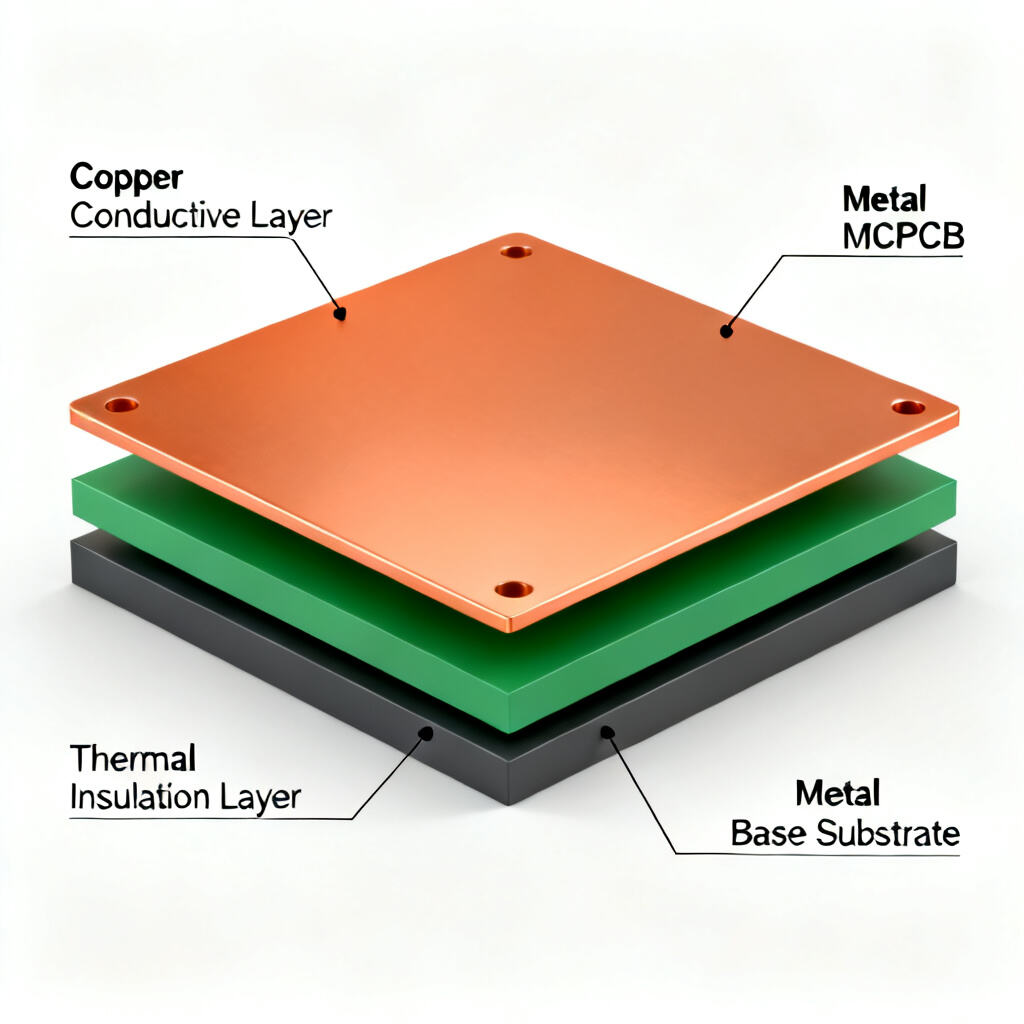 |
It consists of a metal base, a dielectric layer, and a copper circuit layer. | |||
| Double-layer MCPCB structure | 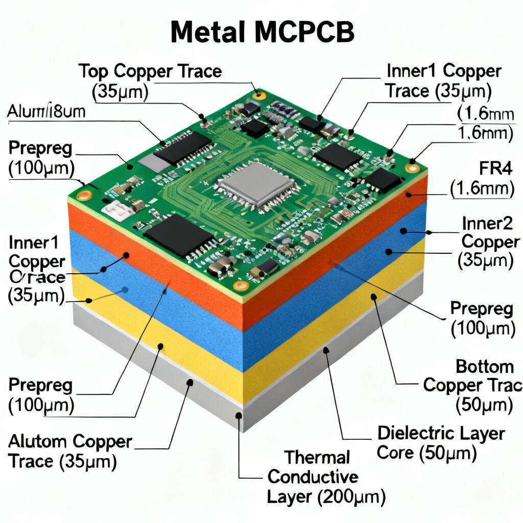 |
It contains two copper layers, with a metal core located between the copper layers, which are interconnected by electroplated vias. | |||
| Multilayer MCPCB structure | 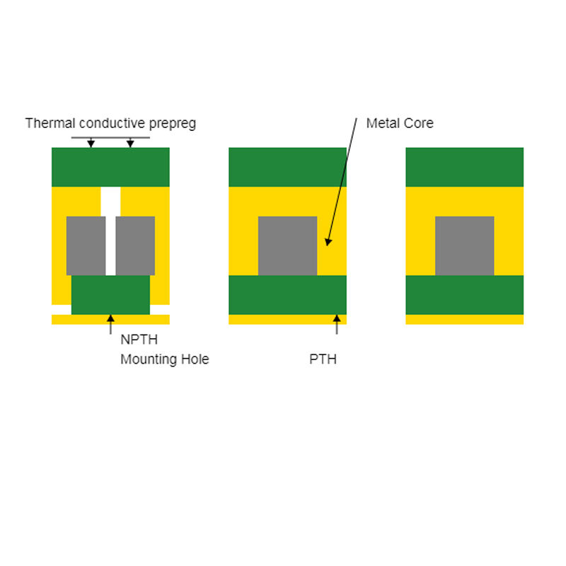 |
It has two or more conductive layers separated by a thermally separated dielectric, with a metal base at the bottom. | |||
Manufacturing capacity
| PCB Manufacturing Capability | |||||
| ltem | Production capability | Min space for S/M to pad, to SMT | 0.075mm/0.1mm | Homogeneity of Plating Cu | z90% |
| Layer Count | 1~40 | Min space for legend to pad/ to SMT | 0.2mm/0.2mm | Accuracy of pattern to pattern | ±3mil(±0.075mm) |
| Production size(Min & Max) | 250mmx40mm/710mmx250mm | Surface treatment thickness for Ni/Au/Sn/OSP | 1~6um /0.05~0.76um /4~20um/ 1um | Accuracy of pattern to hole | ±4mil (±0.1mm ) |
| Copper thickness of lamination | 1/3 ~ 10z | Min size E- tested pad | 8 X 8mil | Min line width/space | 0.045 /0.045 |
| Product board thickness | 0.036~2.5mm | Min space between tested pads | 8mil | Etching tolerance | +20%0.02mm) |
| Auto-cutting accuracy | 0.1mm | Min dimention tolerance of outline (outside edge to circuit) | ±0.1mm | Cover layer alignment tolerance | ±6mil (±0.1 mm) |
| Drill size(Min/Max/hole sizetolerance) | 0.075mm/6.5mm/±0.025mm | Min dimention tolerance of outline | ±0.1mm | Excessive adhesive tolerancefor pressing C/L | 0.1mm |
| Min percent for CNC slot length and width | ≤0.5% | Min R corner radius of outline(inner filleted corner) | 0.2mm | Alignment tolerance forthermosetting S/M and UV S/M | ±0.3mm |
| maximum aspect Ratio(thickness/hole diameter) | 8:1 | Min space golden finger to outline | 0.075mm | Min S/M bridge | 0.1mm |

