Flex PCB Assembly
Precision Flex PCB Assembly for medical/industrial/automotive/consumer electronics. Bendable, space-saving designs paired with 24h prototyping, fast delivery, BOM/DFM support & AOI testing. Reliable soldering for flexible PCBs—accelerate your R&D, reduce risks.
✅ Flexible, compact assembly
✅ 24h prototyping | fast delivery
✅ BOM/DFM & quality testing
Description
What is Flex PCB assembly?
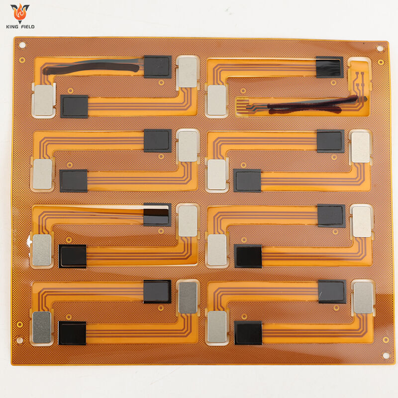
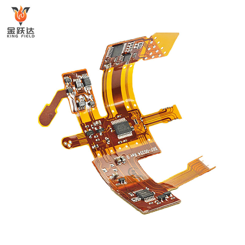
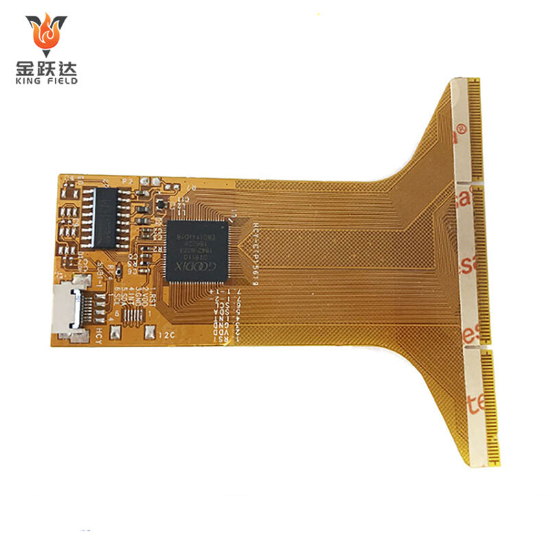
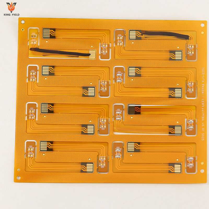
Flex PCB assembly is the process of fixing electronic components such as resistors, capacitors, and chips onto flexible materials such as polyimide using a welding process adapted to flexible substrates. After necessary surface treatment and performance testing, it forms a flexible, thin, and durable functional electronic component suitable for consumer electronics, automotive electronics, medical devices, and other scenarios.
The main tests for Flex PCB Assembly focus on electrical performance, mechanical reliability, soldering and appearance quality, and environmental adaptability, specifically including
1. Continuity test to check circuit continuity and troubleshoot open and short circuits: Verify the correctness of electrical connections.
2. Insulation resistance test to verify the insulation performance between lines.
3. Impedance test to ensure signal transmission quality.
4. Withstand voltage test to prevent high voltage breakdown.
5. Bending test simulating actual working conditions: Evaluate the circuit's ability to withstand repeated bending.
6. Torsion test and tensile test to verify the solder strength of components.
7. AOI inspection to identify defects such as cold solder joints and false solder joints.
8. AXI inspection of the appearance and soldering quality of internal solder joints: Test the component's resistance to temperature fluctuations.
9. And simulated high and low temperature tests and damp heat tests in extreme environments to comprehensively ensure the stable operation of components in complex scenarios.
Applications and Innovations of Flexible Circuit Assembly
Due to its thinness, flexibility, and bend resistance, Flex PCB Assembly is widely used in many industries with high requirements for space adaptability and miniaturization.
Consumer Electronics: Adapts to the irregular structures of foldable phones, smartwatches, wireless headphones, and other devices, enabling compact layouts. Used in cameras, game consoles, and other products, meeting the flexible connection requirements of complex internal circuits.
Automotive Electronics: Used in dashboards, central control screens, and in-vehicle entertainment systems, enabling flexible wiring between components. Adapts to the battery management system (BMS) of new energy vehicles, withstanding vibrations and temperature changes during vehicle operation.
Medical Devices: Used in implantable medical devices, possessing biocompatibility and resistance to the internal environment. Adapts to medical imaging equipment, enabling miniaturized, high-precision circuit integration.
Aerospace Industry: Adapts to drones, aviation sensors, and other equipment, reducing weight and adapting to vibration and shock conditions.
Industrial Electronics: Used in the joints of industrial robots, enabling reliable circuit connections between moving parts. Used in automated testing equipment and sensor modules, meeting the environmental resistance and flexible installation requirements of industrial scenarios.
Flexible PCB Assembly vs. Rigid PCB Assembly: Key Difference
For Kingfield's target audience, understanding the core differences between flexible and rigid PCB assembly is critical for product design, performance, and cost optimization. Below is a structured, industry-specific comparison to highlight key distinctions and guide decision-making:
1. Core Substrate Material
| Aspect | Flexible PCB Assembly (FPCA) | Rigid PCB Assembly (RPCA) | |||
| Base Material | Polyimide (PI) or polyethylene terephthalate (PET) films—thin, lightweight, and bendable. | FR-4, aluminum, or ceramic—rigid, rigid, and dimensionally stable. | |||
| Key Trait | Enables repeated folding, twisting, or conforming to 3D shapes. | Maintains fixed shape; resistant to physical deformation under standard operating conditions. | |||
| Kingfield Advantage | Uses high-grade PI substrates with excellent temperature resistance for harsh environments. | Premium FR-4/low-loss materials for high-frequency applications. | |||
2. Mechanical Performance & Design Flexibility
| Aspect | Flexible PCB Assembly | Rigid PCB Assembly | |||
| Form Factor | Ultra-thin, lightweight. | Thicker, heavier. | |||
| Bendability | Can be folded, rolled, or mounted on curved surfaces. | No flexibility—requires flat mounting. | |||
| Design Freedom | Supports dense component placement, 3D routing, and space-saving in tight enclosures. | Limited to 2D/planar designs; component placement constrained by rigid structure. | |||
| Durability | Resistant to vibration/shock. | Vulnerable to impact. | |||
4. Application Scenarios
| Flexible PCB Assembly | Rigid PCB Assembly | ||||
| Wearable devices E42 | Consumer electronics (smartphones, laptops, TVs) | ||||
| Automotive electronics | Industrial controls (PLCs, motor drivers, factory automation equipment) | ||||
| Aerospace & defense | Medical equipment | ||||
| IoT devices | Data centers B41 | ||||
| Foldable electronics | Power electronics |
5. Kingfield’s Assembly Capabilities Summary
| Service | Flexible PCB Assembly | Rigid PCB Assembly | |||
| Technology | SMT, COB, wire bonding, flexible-rigid hybrid assembly. | SMT, through-hole assembly, mixed-technology, high-frequency routing. | |||
| Quality Control | AOI+ X-ray inspection for hidden solder joints. | AOI, ICT, functional testing for complex assemblies. | |||
| Lead Time | 7–15 business days | 3–10 business days | |||
| Customization | High—supports custom bend radii, 3D routing, and hybrid designs (flex + rigid sections). | Moderate—customizable layouts but limited to rigid form factors. | |||
Decision Guide for Customers Choose Flexible PCB Assembly if:
✅ Your product requires compactness, bendability, or 3D integration.
✅ You’re designing for wearables, automotive, aerospace, or IoT devices.
✅ Vibration/shock resistance is a critical requirement. Choose Rigid PCB Assembly if.
✅ Cost-effectiveness for high-volume production is a priority.
✅ Your product is stationary or requires large/heavy components.
✅ You need a simple, durable solution for standard electronics.
Kingfield offers end-to-end assembly services for both technologies, with engineering support to optimize your design for performance, cost, and manufacturability. Contact our technical team to discuss your specific project needs!
Manufacturing capacity
| Equipment manufacturing process capability | |||||
| SMT Capacity | 60,000,000 chips/day | ||||
| THT Capacity | 1.500,000 chips/day | ||||
| Delivery Time | Expedited 24 hours | ||||
| Types of PCBs Available for Assembly | Rigid boards, flexible boards, rigid-flex boards, aluminum boards | ||||
| PCB Specifications for Assembly | Maximum size: 480x510 mm; Minimum size: 50x100 mm | ||||
| Minimum Assembly Component | 01005 | ||||
| Minimum BGA | Rigid boards 0.3 mm; Flexible boards 0.4 mm | ||||
| Minimum Fine-Pitch Component | 0.2 mm | ||||
| Component Placement Accuracy | ±0.015 mm | ||||
| Maximum Component Height | 25 mm | ||||
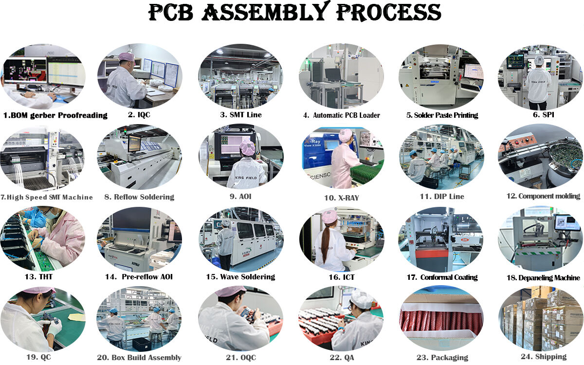
1.Preparation: Clean the flexible substrate, removing surface impurities and checking circuit integrity. Perform surface treatment on the substrate to improve soldering performance and prevent copper oxidation.
2.Component Placement: Use Surface Mount Technology to precisely position SMD components such as resistors, capacitors, and chips onto the designated locations on the substrate. Control pressure and temperature during placement to prevent deformation of the flexible substrate from affecting accuracy.
3.Soldering and Curing: Use reflow soldering to melt and cool the solder paste, achieving a stable connection between the components and the substrate. Some through-hole components require wave soldering to ensure soldering reliability.
4.Inspection and Troubleshooting: Visual Inspection: Use AOI equipment to check for defects such as cold solder joints, bridging, and component misalignment. Internal Inspection: Use X-rays to inspect the solder joint quality of BGA and other packaged components. Electrical Testing: Perform continuity and insulation resistance tests to eliminate short circuits and open circuits.
5.Post-Processing: Perform encapsulation and protection as needed to improve environmental resistance. Fold and shape according to the application scenario; some require layering and lamination. Finally, reliability tests such as bending and high/low temperature tests are conducted to ensure that the product meets the standards.

