Lighting PCB
High-performance Lighting PCBs for commercial/industrial/automotive/consumer lighting systems. Superior thermal management, low power loss & durable design—paired with 24h prototyping, fast delivery, DFM support & AOI testing. Optimized for LED bulbs, strips, fixtures, and smart lighting devices.
✅ Exceptional heat dissipation
✅ Energy-efficient circuitry
✅ LED/smart lighting-specific design support
Description
Overview
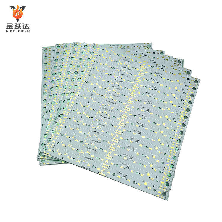
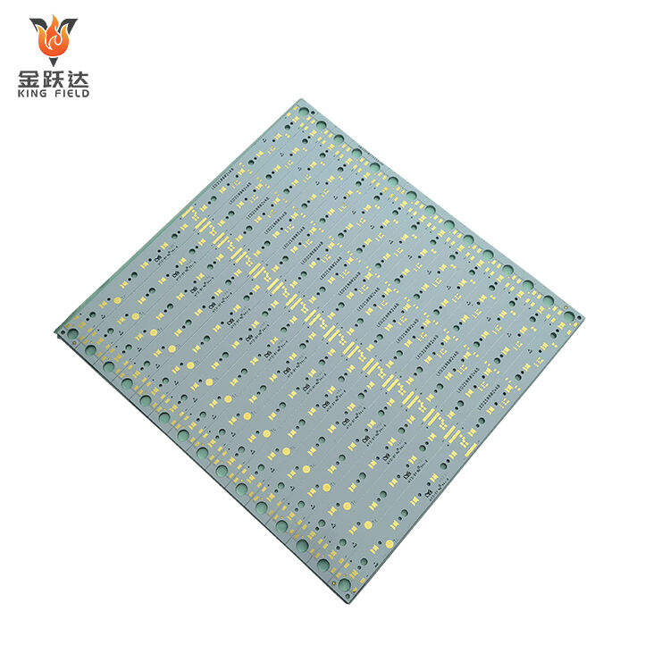
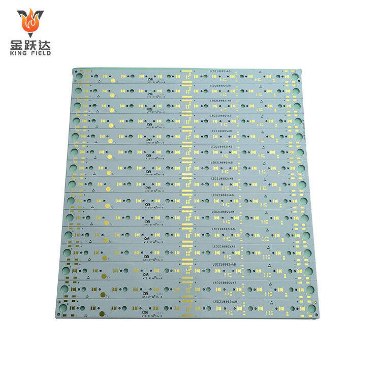
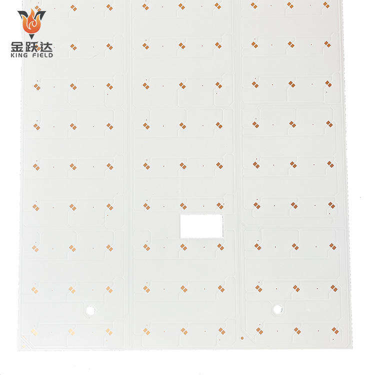
Lighting PCBs are printed circuit boards specifically designed for various lighting products. They are the core carrier and connection components of lighting equipment, mainly used to support LED chips/beads, driver circuit components, and realize power transmission and heat dissipation management. They are suitable for various lighting scenarios such as LED lighting, traditional fluorescent lamp drivers, and solar lighting, with LED lighting PCBs being the mainstream application type at present.
Lighting PCBs are circuit boards custom-designed for the characteristics of lighting equipment. Their core advantages revolve around the heat dissipation, adaptability, and reliability requirements of lighting scenarios, as detailed below:
Targeted heat dissipation design ensures light source lifespan
Mainstream pcb for led have thermal conductivity far exceeding that of ordinary FR-4 PCBs. Aluminum-based PCBs have a thermal conductivity of 1~3 W/(m・K), while copper-based PCBs have a thermal conductivity as high as 200~400 W/(m・K). They can quickly conduct the heat generated by LED chips during operation, preventing light decay and burnout due to overheating, and significantly extending the lifespan of LED lighting equipment. Some high-end ceramic lighting PCBs can also be adapted to the heat dissipation requirements of ultra-high power lighting scenarios.
Adapting to the structural and functional requirements of lighting equipment
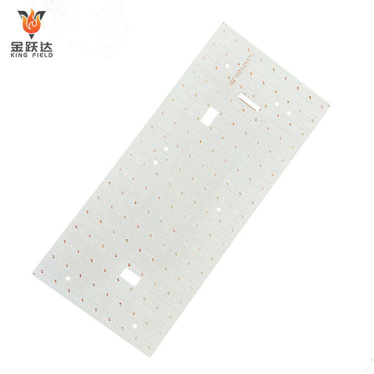
• Flexible shape: Can be customized into ring, arc, flexible or irregularly shaped rigid plate according to the design of the lamp, adapting to the installation space of different lamps such as bulbs, spotlights, and street lights;
• Integrated functions: Supports the integration of LED driver circuit, control circuit and light source circuit on the same PCB, simplifying the internal structure of the lamp and reducing assembly difficulty;
• Package compatibility: Adapts to various LED package forms such as SMD and DIP, meeting the light source installation requirements of different lighting products.
High temperature resistance and environmental reliability
Made with high-temperature resistant substrates and solder resist ink, it can withstand the temperature range of LED operation for a long time (-20~85℃), and some special lighting PCBs can even adapt to extreme environments of -40~125℃ without substrate deformation, circuit aging or solder resist peeling due to high temperature; at the same time, it has good moisture-proof and corrosion-proof properties, and is suitable for various indoor and outdoor lighting scenarios.
Stable electrical performance reduces the risk of failure
Optimized circuit layout reduces the impact of electromagnetic interference on LED luminous stability; the high-power Lighting PCB adopts a widened copper foil and thick copper design to reduce line resistance, avoid voltage drop or overheating of the line when transmitting high current, and ensure the brightness stability and electrical safety of the lighting equipment.
Balance between cost and performance
For civilian lighting applications, the low-cost FR-4 Lighting PCB can be used to meet the needs of low-power LEDs; for medium and high-power applications, aluminum-based PCBs are used to achieve efficient heat dissipation at a moderate cost, balancing performance and economy; standardized production processes reduce mass production costs and facilitate maintenance and replacement, further improving the overall cost-effectiveness.
Meets lighting industry safety standards
Strictly adhere to the insulation and flame retardant standards for lighting equipment to prevent safety hazards such as short circuits and fires, especially in commercial and industrial lighting scenarios, meeting high safety requirements.
Contrast
Lighting PCB and LED PCB are not entirely independent concepts; they have a relationship of inclusion and being included, and general and specific applications. The core differences and connections can be clearly distinguished from dimensions such as definition, scope, and characteristics:
Core Definitions and Scope Differences
Lighting PCB
This is a general term for PCBs specifically designed for all types of lighting equipment, covering all lighting types . Their core function is to provide circuit connections, component support, and heat dissipation management for various lighting products, adapting to the operating characteristics of different light sources.
Scope: Includes PCBs for LED lighting, fluorescent lamp ballasts, incandescent lamp dimming, and other circuit boards for all lighting scenarios.
LED PCB
This is a PCB specifically designed for LED light sources, belonging to a subcategory of lighting PCBs. It serves only LED lighting equipment (such as LED bulbs, spotlights, streetlights, and light strips), and needs to match the low voltage, high current, and high heat generation characteristics of LEDs.
Scope: Only for LED lighting scenarios, it is a core component of lighting PCBs (accounting for over 90%, as LEDs are currently the mainstream lighting source).
| Dimension | Lighting PCB | LED PCB | |||
| Applicable light source | All lighting sources | LED light source only | |||
| Core Design Focus | Adaptable to the electrical characteristics of different light sources. | Prioritizing heat dissipation + Low-voltage, high-current circuit design | |||
| Substrate selection | Fluorescent/incandescent lamp drivers can use standard FR-4; aluminum/copper based drivers are used for LED applications. | Mainly aluminum-based and copper-based, FR-4 is used for low power, and ceramic is used for high-end. | |||
| Functional requirements | Emphasis is placed on circuit control. | It takes into account circuit connection, heat dissipation, and structural adaptation. | |||
Relevance and Practical Application
Inclusion relationship: LED PCB is the core sub-category of lighting PCB. As LEDs replace traditional light sources, more than 95% of lighting PCBs on the market are currently LED PCBs. Therefore, in everyday language, "lighting PCB" is often directly equated with "LED PCB", but strictly speaking, the two have different scopes.
Design differences:
Traditional lighting PCBs: No strong heat dissipation is required; FR-4 substrate is sufficient. The focus should be on optimizing the insulation of the high-voltage drive circuit.
LED PCBs: Heat dissipation must be prioritized. The circuitry must be adapted to the constant current drive characteristics of LEDs to avoid light decay caused by current fluctuations.
Overlapping scenarios: All LED PCBs belong to the category of lighting PCBs, but not all lighting PCBs are LED PCBs.
Types of lighting PCBs
| Type | Specific types | characteristic | Advantages | Applicable Scenarios | |
| Substrate material | FR-4 Lighting PCB | With a thermal conductivity of 0.3-0.5 W/(m·K), mature technology, good insulation, and low cost, this product boasts a mature manufacturing process. | High cost performance and simple processing | Low-power LED indicator lights, traditional fluorescent lamp ballasts, small desk lamps | |
| Aluminum-based lighting PCB | Thermal conductivity 1.0-4.0 W/(m·K), high mechanical strength, and better heat dissipation than FR-4. | Good balance between heat dissipation and cost | Medium and high power LED panel lights, street lights, industrial spotlights | ||
| Copper-based lighting PCB | Thermal conductivity of 200-400 W/(m·K), strong current carrying capacity, and excellent heat dissipation. | Suitable for ultra-high power and high temperature conditions | Stage lights, car headlights, industrial searchlights | ||
| Ceramic Lighting PCB | Alumina type has a thermal conductivity of 15-30 W/(m·K), high temperature resistance, and excellent insulation. | Highly stable and adaptable to extreme environments | Medical surgical lights, explosion-proof lights, high-temperature special lighting | ||
| Flexible (PI) lighting PCB | Polyimide substrate, flexible and bendable, thin and light | Adaptable to irregular structures, flexible wiring | LED flexible light strips, automotive interior ambient lighting, curved lighting fixtures | ||
| Structural form | Rigid lighting PCB | It has a fixed and rigid shape, stable structure, and is resistant to wear and tear. | Easy to install and has a strong load-bearing capacity | Ceiling lights, street lights, and general fixed lighting equipment | |
| Flexible lighting PCB | Soft, flexible, foldable, and lightweight | Adapting to irregular spaces | Flexible light strips, curved taillights for automobiles | ||
| Rigid-flexible lighting PCB | The rigid area supports the components, while the flexible area connects the light source. | Balancing stability and flexibility | Internal connections of automotive headlights, irregular wiring for intelligent lighting | ||
| Types of lighting sources | LED lighting PCB | Low voltage and high current require heat dissipation design; the substrate is mostly metal-based/flexible. | Adapted to LED light-emitting characteristics, preventing light decay | Full range of LED lighting products | |
| Lighting PCBs for Fluorescent Lamps | High-voltage drive, no need for strong heat dissipation, focus on insulation | Adapt to fluorescent lamp ballast requirements | Various fluorescent lamp driver control boards | ||
| Lighting PCBs for Incandescent/Halogen Lamps | Low power consumption and low heat generation; emphasis is placed on the stability of the dimming circuit. | It supports dimming function and has a low cost. | Dimmable incandescent and halogen lamp control board | ||
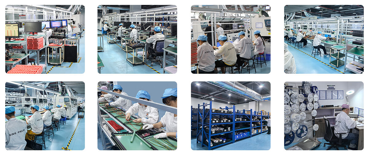
Manufacturing Capacity
| Rigid RPCB Manufacturing Capability | |||||
| Item | RPCB | HDI | |||
| minimum linewidth/linespacing | 3MIL/3MIL(0.075mm) | 2MIL/2MIL(0.05MM) | |||
| minimum hole diameter | 6MIL (0.15MM) | 6MIL (0.15MM) | |||
| minimum solder resist opening (single-side) | 1.5MIL (0.0375MM) | 1.2MIL (0.03MM) | |||
| minimum solder resist bridge | 3MIL (0.075MM) | 2.2 MIL (0.055 mm) | |||
| maximum aspect ratio (thickness/hole diameter) | 0.417361111 | 0.334027778 | |||
| impedance control accuracy | +/- 8% | +/- 8% | |||
| finished thickness | 0.3-3.2MM | 0.2-3.2MM | |||
| maximum board size | 630mm*620mm | 620mm*544mm | |||
| maximum finished copper thickness | 6 oz (210 μm) | 2 oz (70 μm) | |||
| minimum board thickness | 6MIL (0.15MM) | 3MIL (0.076MM) | |||
| maximum layer | 14th floor | 12 floors | |||
| Surface treatment | HASL-LF, OSP, Immersion Gold, Immersion Tin, Immersion Ag | Immersion Gold、OSP、selectiveimmersion gold、 | |||
| carbon print | |||||
| Mini/max laser hole size | / | 3MIL / 9.8MIL | |||
| laser hole size tolerance | / | 0.1 | |||
Precautions
Lighting PCB design needs to balance heat dissipation, electrical performance, structural compatibility, and industry standards. The core challenges lie in thermal management and electromagnetic compatibility, with the following key considerations: Core Design Challenges
Thermal management challenges
• Challenges: LEDs and other light sources generate concentrated heat during operation. Poor heat dissipation can lead to accelerated light decay, shortened lifespan, and even component burnout. Traditional FR-4 substrates have poor thermal conductivity, requiring a balance between heat dissipation and cost in metal-based PCB designs.
• Root Causes: Lighting PCBs are space-constrained, making it difficult to arrange large heat dissipation structures. Different light sources have significantly different heating characteristics, necessitating targeted optimization of heat dissipation designs.
Electromagnetic Interference (EMI) Issues
• Challenges: Driver circuits are prone to generating electromagnetic radiation, which can interfere with the control signals of lighting equipment or surrounding electronic devices. Furthermore, lighting PCBs must meet EMC certification requirements.
• Root Causes: Lighting PCBs often integrate power supply, control, and light source circuitry, with high and low voltage circuits coexisting, making electromagnetic coupling easy. The small size design results in close spacing between traces, increasing the risk of interference.
Structure and installation compatibility
• Challenges: Lighting fixtures come in various shapes (ring-shaped, curved, ultra-thin), requiring lighting PCBs to match these irregular structures while ensuring a compact component layout; outdoor lighting PCBs also need to meet waterproof, dustproof, and vibration resistance requirements.
• Root Cause: Civil/commercial lighting fixtures have stringent requirements for appearance and size, necessitating PCB designs that balance electrical functionality with mechanical installation.
Electrical safety and reliability
• Challenges: Lighting PCBs involve mains power access and low-voltage light sources. Inadequate isolation between high and low voltage can easily lead to leakage and short circuits. Long-term operation in high-temperature/humid environments can cause circuit aging and solder joint failure.
• Root Causes: Lighting equipment is used in complex scenarios with high safety standards.
Key Design ConsiderationsSubstrate selection:
• Low-power lighting: FR-4 substrate is used, and heat dissipation is aided by increasing the copper area;
• Medium and high-power lighting: aluminum-based PCB is preferred, and copper-based or ceramic PCB is used for ultra-high power;
• Flexible lighting: high thermal conductivity PI substrate is used, with aluminum heat sink backing.
Circuit and pad design:
The LED pads adopt a "thermal conductive pad" design to increase the contact area with the substrate and quickly conduct heat;
the high-power circuit uses wider copper foil and thicker copper (2oz and above) to reduce resistance and heat generation;
large areas of copper foil are avoided to reduce PCB warping caused by thermal stress.
Layout optimization:
Heat-generating components are distributed to avoid heat concentration; the driver circuit and light source circuit are arranged separately to prevent heat from the driver IC from being transferred to the LED.
Electromagnetic compatibility design considerations
Line isolation:
The distance between high and low voltage lines is ≥3mm, and the mains power line and the low voltage light source line are isolated by an insulating groove;
EMI filters are added to the input/output terminals of the drive circuit to suppress electromagnetic radiation.
Grounding design:
Single-point grounding is used to avoid forming grounding loops;
the metal substrate of a metal-based PCB needs to be grounded to enhance the shielding effect;
sensitive components should be placed close to the grounded copper foil to reduce interference.
Wiring rules:
High-frequency lines are short and straight to avoid circuitous wiring;
power lines and signal lines cross perpendicularly to reduce electromagnetic coupling.