LED PCB
High-performance LED PCBs for lighting applications (commercial/industrial/automotive/consumer). Superior thermal management, low thermal resistance, and reliable conductivity—paired with 24h prototyping, fast delivery, DFM support & AOI testing. Durable, energy-efficient, and tailored for LED bulbs, strips, fixtures.
✅ Exceptional heat dissipation
✅ DFM optimization & quality validation
✅ LED lighting-specific design support
Description
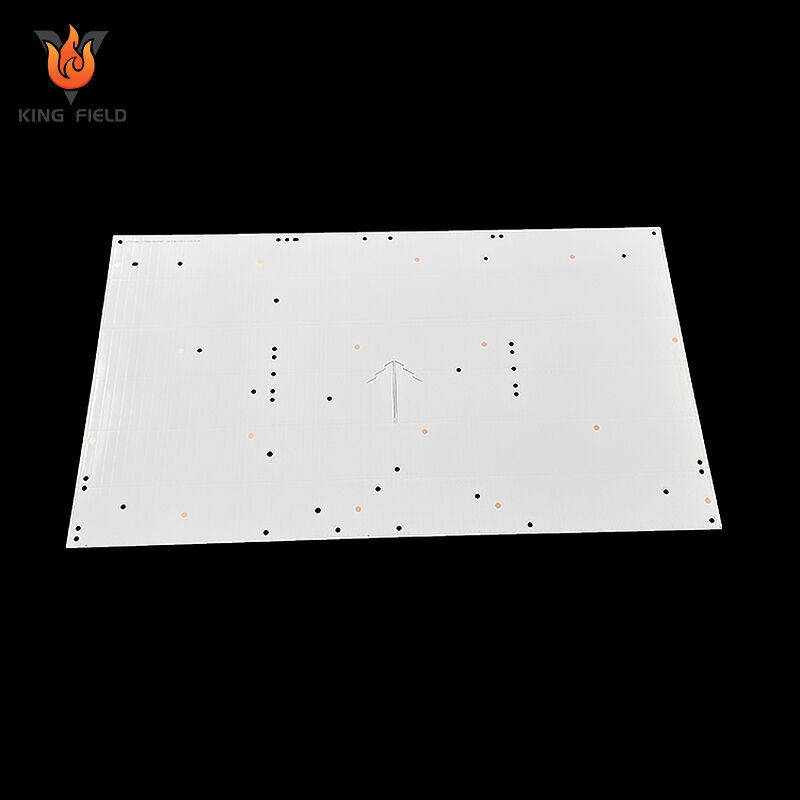
What is an LED PCB?
An LED PCB is a printed circuit board specifically designed for light-emitting diode devices. Its core function is to provide mechanical support and electrical connection for LED chips. At the same time, it efficiently dissipates the heat generated by the LED during operation through high thermal conductivity substrates such as aluminum-based, copper-based, and ceramic-based materials, avoiding light attenuation and shortened lifespan. Its circuits mostly adopt a series + parallel hybrid topology, with the line width matching the working current of the LED. It can also be designed in rigid, flexible or a combination of soft and hard forms according to application requirements and support irregular cutting. It is compatible with leds of different packages such as SMD 2835 and 5050, and is widely used in general lighting, automotive electronics, backlight display, special lighting and other scenarios. The core difference from ordinary PCBS lies in that the former takes heat conduction and dissipation as well as electrical connection as its core requirements, while the latter only needs to meet the basic electrical connection.
Advantages of LED PCB
Efficient heat dissipation solves the problems of LED light attenuation and lifespan from the root
When leds are in operation, their electrical energy conversion efficiency is limited. Approximately 80% of the electrical energy is converted into heat. The accumulation of heat directly leads to an increase in the temperature of the LED chip, causing problems such as accelerated light attenuation, color temperature drift, and shortened lifespan.
· Thermal conductivity advantage of the base material:
The led pcb board adopts high thermal conductivity substrates such as aluminum-based, copper-based, and ceramic-based materials, with thermal conductivity far exceeding that of ordinary FR-4 PCBS (the thermal conductivity of FR-4 is approximately 0.3 W/(m · K), that of aluminum-based can reach 1-20 W/(m · K), and that of aluminum nitride ceramic can reach 180-200 W/(m · K)). It can quickly conduct the heat generated by the LED chip to the heat sink or the external environment.
· Structural heat dissipation optimization:
Some high-power led circuit board are designed with heat-conducting pads and metallized vias to enhance the heat conduction efficiency from the surface LED pads to the bottom metal substrate. Aluminum-based PCBS can also be directly bonded to heat sinks without the need for additional thermal conductive adhesives, further reducing thermal resistance.
· Practical value:
Reasonable heat dissipation can extend the lifespan of leds from several thousand hours to 50,000 to 100,000 hours, while ensuring the long-term stability of luminous brightness and color temperature. It is particularly suitable for scenarios that require continuous operation for long periods, such as street lamps and car headlights.
The circuit topology is stable, enhancing the overall board's resistance to faults
The circuit design of the led light circuit board fully takes into account the characteristics of leds that "series connection is prone to open circuit and parallel connection is prone to current diversion", while balancing reliability and brightness consistency.
· Advantages of series-parallel hybrid topology:
It adopts a circuit structure of "multiple groups in series + overall parallel". If a single LED is disconnected, it will only affect the series branch where it is located and will not cause the entire board to go out. At the same time, the parallel structure can ensure that the voltages of each branch are consistent, preventing some leds from being burned out due to excessive current.
· Current matching design:
Precisely design the line width and copper foil thickness based on the rated operating current of the LED to prevent current loss caused by wire heating or excessive resistance. For high-power leds, current-limiting resistor pads will also be reserved to facilitate the adjustment of current according to actual needs.
· Practical value:
The failure rate of the entire board has been significantly reduced, requiring no frequent maintenance. It is suitable for scenarios with high stability requirements such as home lighting and commercial lighting.
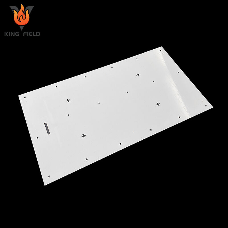
It is flexible in form and structure, suitable for a wide range of application scenarios
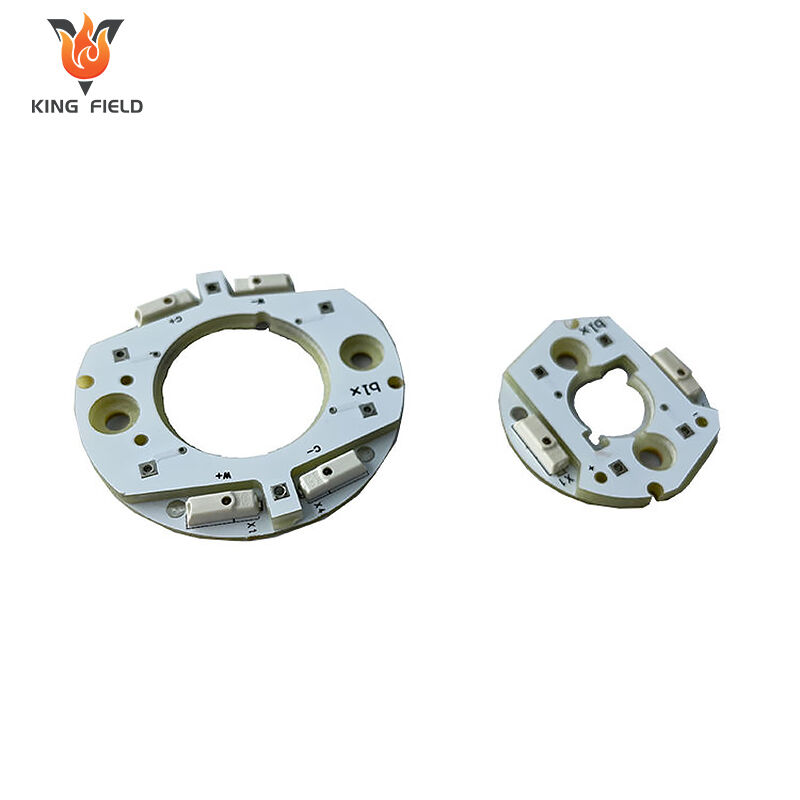
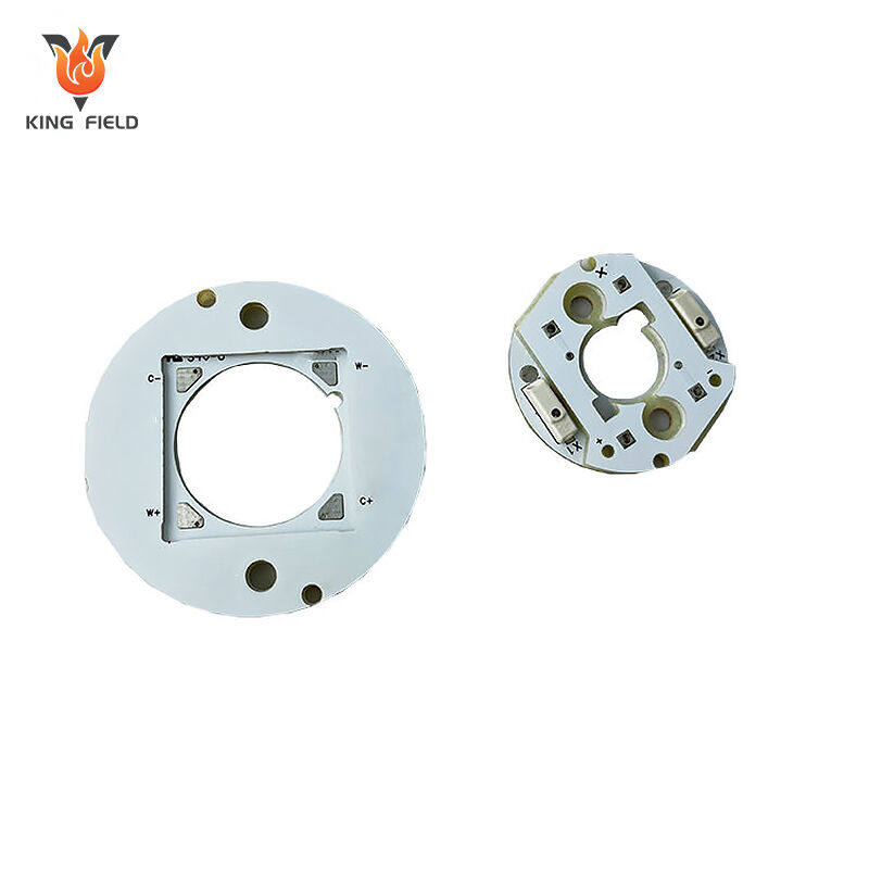
LED PCB breaks through the rigidity limitation of ordinary PCB and can be customized according to the shape requirements of different lighting products
· Morphological diversity: Supports three forms: rigid, flexible, and a combination of soft and hard. Rigid LED PCBS are suitable for fixed-shaped lamps such as bulbs and spotlights. The flexible led circuit board can be bent and folded, making it suitable for various irregular scenarios such as automotive ambient lighting and curved screen backlighting. The rigid-flex board takes into account both the bending requirements of the flexible area and the device load-bearing capacity of the rigid area.
· Irregular cutting and integrated design: Any shape such as circular, arc-shaped, and strip-shaped can be achieved through laser cutting, which is suitable for different lamp housings. It can also integrate drive circuits and sensors to achieve an integrated "PCB + drive + sensing" model, reducing product volume and assembly processes.
· Practical value: It meets the demands of all scenarios, from micro indicator lights to large outdoor displays, and facilitates the miniaturization and lightweight design of products.
Balance cost and performance to meet the demands of different markets
LED PCB offers a variety of substrate solutions, which can be flexibly selected according to the customer's budget and performance requirements
· High cost-performance solution: The cost of aluminum LED PCBS is only 1/3 to 1/2 of that of copper-based ones, and their thermal conductivity meets over 80% of the lighting requirements for household use. It is the preferred choice for household ceiling lamps and panel lamps.
· High-performance solutions: Copper-based and ceramic led circuit board have stronger thermal conductivity, are resistant to high temperatures and corrosion, and are suitable for harsh scenarios such as automotive-grade leds and industrial control equipment indicator lights.
· Low-cost solution: Low-power LED indicator lights can adopt FR-4 substrate LED PCBS, which have the lowest cost and meet the requirements of low-power consumption scenarios such as toys and small household appliances.
· Practical value: Covering the entire price range from low-end to high-end markets, helping customers achieve target performance while controlling costs.
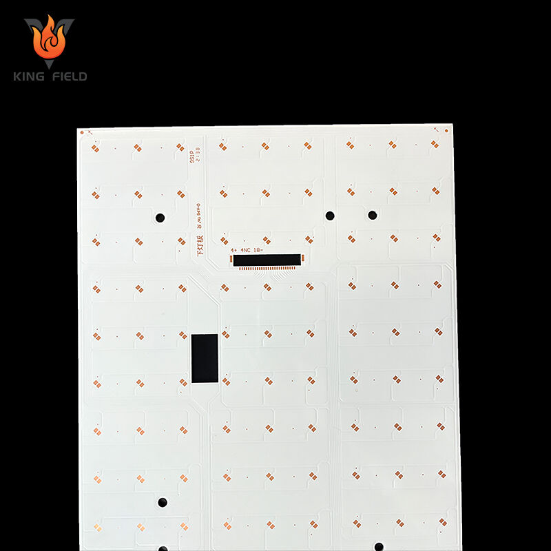
High compatibility, compatible with multiple LED packaging types
The pad design of the led circuit board is compatible with mainstream LED packaging specifications and does not require separate mold opening.
It supports various types of SMD packaging, COB packaging, high-power lumen-like packaging, etc. The size and pitch of the solder pads can be customized according to the LED specifications.
For COB LED PCBS, reflective coatings or metal reflectors will also be designed to enhance light utilization and increase lighting brightness.
Types of LED PCBs
LED PCBs can be classified based on substrate material, structural form, and LED package compatibility.
Different types vary in heat dissipation performance, cost, and application scenarios, as detailed below:
Classification by Substrate Material
This is the most mainstream classification method, directly related to the product's heat dissipation efficiency and applicable power range.
| Type | Core Composition | Thermal Conductivity | Advantages | Application Scenarios | |
| Aluminum-based LED PCB | Insulation layer + Aluminum substrate + Circuit layer | 1–20 W/(m·K) | High cost-effectiveness, moderate heat dissipation, easy processing | Household lighting (ceiling lights/bulbs), commercial lighting (spotlights/panel lights), automotive interior lights | |
| Copper-based LED PCB | Insulation layer + Copper substrate + Circuit layer | 200–400 W/(m·K) | Excellent thermal conductivity, high temperature resistance | High-power LEDs (street lights/industrial lights), automotive headlights, industrial heating lamps | |
| Ceramic-based LED PCB | Alumina/aluminum nitride ceramic substrate + Circuit layer | 20–200 W/(m·K) (higher for aluminum nitride) | Good insulation, strong heat dissipation, superior corrosion resistance | Automotive-grade LEDs, medical equipment indicator lights, high-frequency LED driver modules | |
| FR-4-based LED PCB | Standard FR-4 substrate + Circuit layer | Approximately 0.3 W/(m·K) | Ultra-low cost | Low-power LEDs (toy indicator lights, small household appliance power indicators) | |
Classification by Structural Form
Classified according to product installation and shape requirements, determines the spatial adaptability of LED PCBs.
Rigid LED PCB
Fixed shape, non-bendable, with high mechanical strength. It is the most common type, suitable for most fixed-installation lamps.
Flexible LED PCB (FPC-LED)
Uses flexible substrates, can be bent, folded, and rolled. Suitable for special-shaped or curved lighting scenarios, such as automotive ambient lights, light strips, and curved screen backlights.
Rigid-Flex LED PCB
Rigid areas carry LED chips and driver components, while flexible areas enable bending. It balances stability and flexibility, applicable to lamps with complex structures.
Classification by LED Package Compatibility
SMD LED PCB
Pad design is compatible with surface-mount device LEDs. It features mature technology and high automation, making it the mainstream type in the current market.
COB LED PCB
Designed specifically for Chip-on-Board LEDs. LED chips are directly mounted on the PCB surface without brackets or gold wires, offering a wide luminous angle and uniform brightness. Suitable for spotlights, downlights, and other lamps with high light spot requirements.
High-power LUXEON LED PCB
Features larger pad areas and shorter heat dissipation paths, compatible with single high-power LEDs (≥1W). Commonly used in outdoor lighting and industrial lighting applications.
Application
LED PCBS, with their features of efficient heat dissipation, stable circuits, and flexible forms, are widely used in various scenarios that rely on LED light emission, covering general lighting, automotive electronics, backlight displays, special lighting, industrial control, medical and other fields. The specific applications are as follows:
General lighting field
This is the most core application scenario of led pcb board, suitable for both household and commercial lighting equipment:
· Household lighting: Ceiling lamps, bulb lamps, table lamps and downlights mostly adopt aluminum-based rigid LED PCBS, which take into account both heat dissipation and cost performance.
· Commercial lighting: Shopping mall spotlights, store track lights, office building panel lights, outdoor street lamps/garden lamps. High-power street lamps will use copper led light pcb board to enhance heat dissipation and ensure long-term working stability.
The field of automotive electronics
It meets the strict requirements of automotive-grade high-temperature resistance and vibration resistance, and is divided into two types: inside and outside the vehicle.
· Interior lighting: Ambient lighting, reading lights, and dashboard backlighting are mostly equipped with flexible LED PCBS, which are suitable for curved surfaces and irregular installation Spaces.
· Exterior lighting: For headlights, turn signals, brake lights, and fog lights, ceramic or copper-based LED PCBS should be selected to withstand temperature cycles ranging from -40 ° C to 125 ° C and vibration environments.
Backlight Display Field
Backlight systems supporting various screens require high demands on form factor and brightness uniformity:
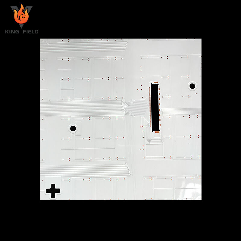
Consumer Electronics Backlighting: Screen backlighting for mobile phones, tablets, and laptops, using flexible LED PCBs or ultra-thin rigid LED PCBs to achieve lightweight and thin designs;
Commercial Display Backlighting: LCD TVs, advertising machines, and outdoor displays, using COB LED PCBs to improve brightness uniformity and reduce light spot issues.
Special Lighting Field
Adapting to customized and functional lighting needs:
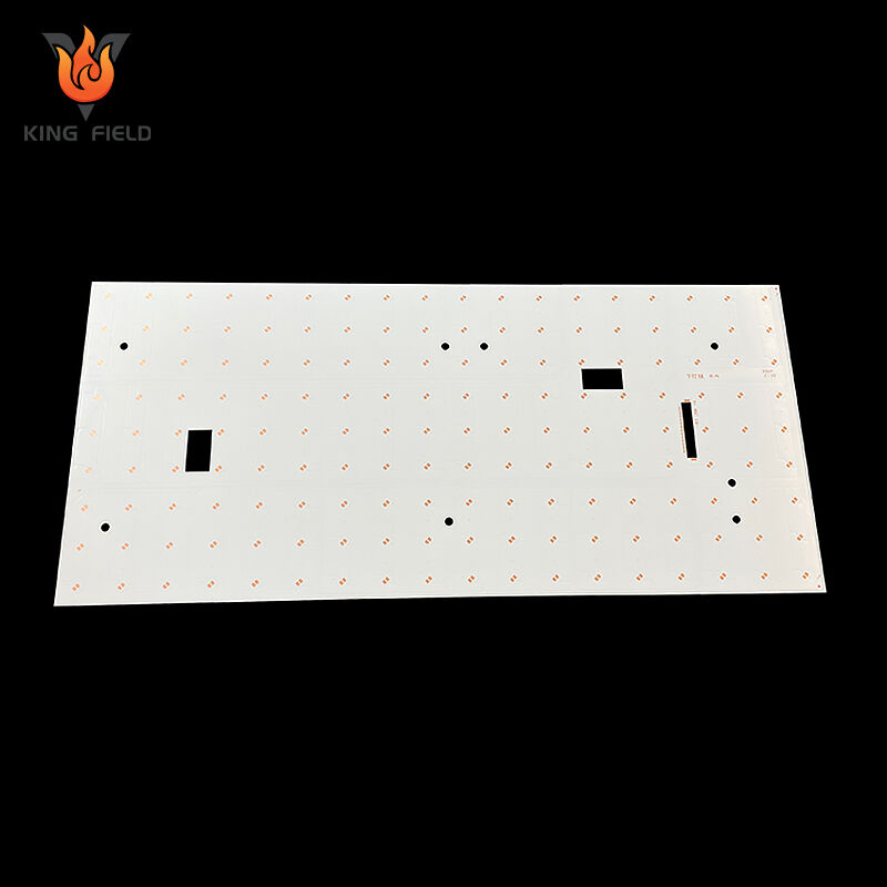
Plant Growth Lights: Using high-thermal conductivity aluminum-based LED PCBs to carry high-power LED beads, meeting the spectral and thermal requirements for plant photosynthesis;
Ultraviolet Sterilization Lamps: Using corrosion-resistant substrate LED PCBs, suitable for ultraviolet irradiation environments;
Stage Lights / Landscape Lights: Achieving diverse lighting shapes and dynamic effects through irregularly shaped led board circuit and flexible-rigid combination boards.
Industrial Control and Medical Equipment Field
Meeting high reliability and high stability requirements:
Industrial Control Equipment: CNC machine tool indicator lights, industrial equipment status warning lights, using ceramic-based led pcb board to adapt to high temperature, dust, and vibration interference in industrial environments;
Medical Equipment: Surgical shadowless lamps, medical testing instrument backlights, portable medical equipment indicator lights, requiring compliance with medical certification standards and using low electromagnetic interference led board circuit designs.
Manufacturing Capabilities
| PCB Manufacturing Capability | |||||
| ltem | Production capability | Min space for S/M to pad, to SMT | 0.075mm/0.1mm | Homogeneity of Plating Cu | z90% |
| Layer Count | 1~40 | Min space for legend to pad/ to SMT | 0.2mm/0.2mm | Accuracy of pattern to pattern | ±3mil(±0.075mm) |
| Production size(Min & Max) | 250mmx40mm/710mmx250mm | Surface treatment thickness for Ni/Au/Sn/OSP | 1~6um /0.05~0.76um /4~20um/ 1um | Accuracy of pattern to hole | ±4mil (±0.1mm ) |
| Copper thickness of lamination | 1/3 ~ 10z | Min size E- tested pad | 8 X 8mil | Min line width/space | 0.045 /0.045 |
| Product board thickness | 0.036~2.5mm | Min space between tested pads | 8mil | Etching tolerance | +20%0.02mm) |
| Auto-cutting accuracy | 0.1mm | Min dimention tolerance of outline (outside edge to circuit) | ±0.1mm | Cover layer alignment tolerance | ±6mil (±0.1 mm) |
| Drill size(Min/Max/hole sizetolerance) | 0.075mm/6.5mm/±0.025mm | Min dimention tolerance of outline | ±0.1mm | Excessive adhesive tolerancefor pressing C/L | 0.1mm |
| Warp&Twist | ≤0.5% | Min R corner radius of outline(inner filleted corner) | 0.2mm | Alignment tolerance forthermosetting S/M and UV S/M | ±0.3mm |
| maximum aspect Ratio(thickness/hole diameter) | 8:1 | Min space golden finger to outline | 0.075mm | Min S/M bridge | 0.1mm |